a) Draw (two) qualitatively correct phasor diagrams that show the
voltage drops and gains for each of the two loops shown. Be sure to
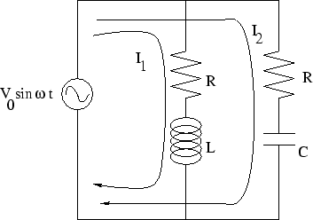
correctly indicate the phases of the currents ![]() and
and ![]() relative
to the phase of the applied voltage and the voltage drop across each
element.
relative
to the phase of the applied voltage and the voltage drop across each
element.
b) Write the Kirchoff's Law (Voltage) for each of the two loops shown that corresponds to your phasor diagram.
c) From a) and b), find the impedance of each loop ![]() and
and ![]() ,
the current phase of each loop
,
the current phase of each loop ![]() and
and ![]() , and write
down an expression for
, and write
down an expression for ![]() and
and ![]() . Try to work neatly
enough that I can grade this.
. Try to work neatly
enough that I can grade this.
d) For extra credit, use Kirchoff's Law (current) to find the total
impedance of the circuit, the total current provided by the voltage,
and the total power provided by the voltage.