
| This page has been started as part of the process to document and present the modifications we have made to various components within the Coherent 899-21 laser system installed in our lab. Before implementing these changes we were measuring laser linewidths between 3 and 5 MHz (FWHM) using standard scanning and fixed-length cavity techniques with various reference cavities including the laser's own on board reference cavity. Recent measurements, after the following modifications, have been consistently within 0.8-1.0 MHz. Changes in the pump laser (see below) resulted in a linewidth of 0.25 MHz or 250 kHz. |
Skip to:Linewidth Measurements Equipment Used Acoustic Considerations Electronic Consierationd |
The Coherent 240 scanning cavity is a stand-alone reference cavity which allows for independent movement of the cavity relative to the laser source and associated optics. To reduce such relative movement the cavity, optics, and fiber mount were magnetically attached to 1/2" steel plating which in turn was isolated from the table with the vibration reducing rubber. Additionally we noted improvement after re-routing the optical fiber to avoid instrument fans and other sources of air currents or vibration.
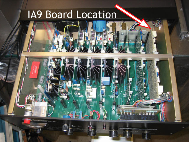 The 899-21 control box (left) uses a modular circuit board design where 9
individual boards are plugged into a motherboard. The slots on the
motherboard are labeled with each board identifier and name. Our
modifications were all on the IA9 board which, if you are facing the
control panel, is the right-most board in the box (pictured at right).
The 899-21 control box (left) uses a modular circuit board design where 9
individual boards are plugged into a motherboard. The slots on the
motherboard are labeled with each board identifier and name. Our
modifications were all on the IA9 board which, if you are facing the
control panel, is the right-most board in the box (pictured at right).
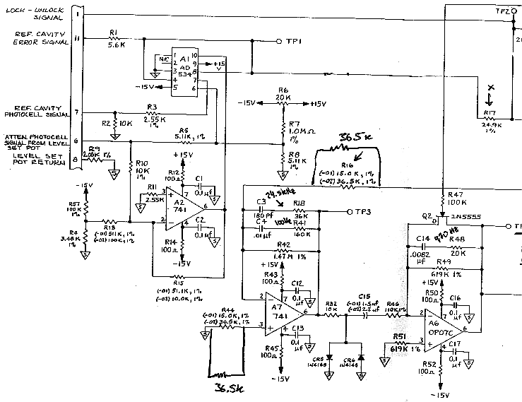
 This board is responsible for processing an error signal and sending the
appropriate control signals to the high and low frequency correction
devices (tweeter and woofer). The full schematic of this board is identical
to that for the Coherent 699-21 a scan of which is included to the right.
Our only electronic modification was in the initial tweeter gain stage
which uses amplifier A7. A closeup of the marked changes is shown below.
This board is responsible for processing an error signal and sending the
appropriate control signals to the high and low frequency correction
devices (tweeter and woofer). The full schematic of this board is identical
to that for the Coherent 699-21 a scan of which is included to the right.
Our only electronic modification was in the initial tweeter gain stage
which uses amplifier A7. A closeup of the marked changes is shown below.

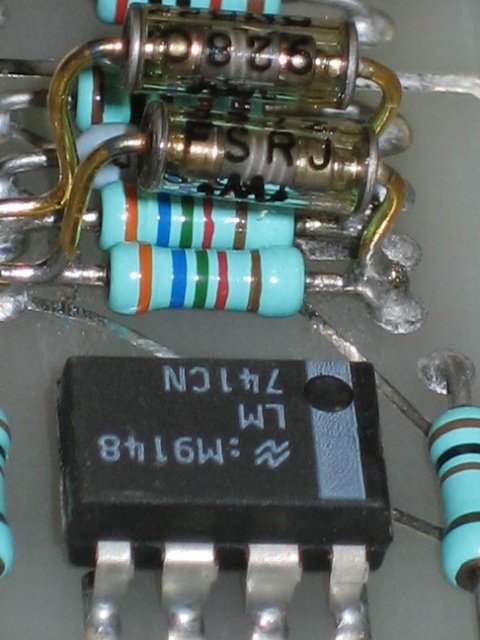
 We changed the resistance of two resitors in the tweeter gain stage at
amplifier A7. Resistors R16 and R44 were bridged with 36.5k resistors to
create an effective resistance of half their original value (about 18k).
Note this nearly restores the value specified in the Coherent 599 control
circuit (15.0k) which is known to operate well at a narrower linewidth.
These basic circuit modifications led to a dramatic increase in laser
stability by increasing the stabilization circuit's response to errors in
the laser's output frequency.
We changed the resistance of two resitors in the tweeter gain stage at
amplifier A7. Resistors R16 and R44 were bridged with 36.5k resistors to
create an effective resistance of half their original value (about 18k).
Note this nearly restores the value specified in the Coherent 599 control
circuit (15.0k) which is known to operate well at a narrower linewidth.
These basic circuit modifications led to a dramatic increase in laser
stability by increasing the stabilization circuit's response to errors in
the laser's output frequency.